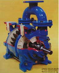
Liquid Ring Vacuum Pumps

Theory of Operation

A liquid ring vacuum pump has an impeller with blades attached to a center hub. The blades are located in the cylindrical body, but are off-set from the center.

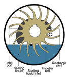
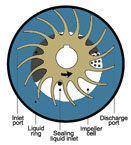
In Figure 1 to the right, you can see the blades near the top of the pump are closer to the outside wall than at the sides and bottom of the pump. You can see this more clearly in Figure 2.

The impeller sits between two end plates (port plates) which have shaped holes cut into them called ports.

The pump requires a liquid (also called the sealant) to create vacuum as follows. Prior to starting, the pump is partially filled with the liquid sealant. The liquid can be water (making it a water ring pump), oil or a solvent, depending upon the application.
liquid ring vacuum pumps | how it works
Figure 1
liquid ring vacuum pumps | how it works
Figure 2

Liquid Ring Vacuum Pump

One Cycle of a Single-Stage Liquid Ring Pump

When the pump first starts, centrifugal force slings the liquid sealant from the impellers to the outside walls of the body. This forms a ring of liquid on the outside of the body. The offset design causes some blades to be fully immersed while some are almost out of the liquid. The area of void space seals off between the liquid (hence the name “sealant”) and the impeller blades. This area is an “impeller cell.”

Following one impeller cell from the top of the pump, counter-clockwise, you can see the liquid recedes from the center hub. The sealant acts as a liquid piston to create a larger cell. This is the suction of the pump because it draws in air, gases, or vapors through the “inlet port” at the sides of the impeller. The impeller cell passes the inlet port and travels toward the discharge port which forces the sealant liquid toward the center hub of the impeller. This creates the compression step.

As the impeller cell passes the discharge port, the compression is at its highest because the impeller cell is at its lowest volume. The discharge port exhausts the gases, along with some of the liquid sealant, to atmospheric pressure. Although the diagrams show a very smooth ring of liquid, in actuality, the liquid sealant is highly turbulent. This results in some of the liquid sealant being discharged with the gases.

Single-Stage vs Two-Stage

The above describes the cycle of a single-stage pump. In one revolution, we have suction (pulling a vacuum), and compression (back to atmosphere). Some manufacturers’ single-stage pumps can operate to just 26″HgV, while others can operate to 28″HgV. Some can even pull down to 29″HgV. A two-stage pump design means there are two single-stage pumps operating in series. The discharge of the first stage goes into the suction port of the second stage. Two-stage pumps have better efficiency at higher vacuum levels (higher than 23″HgV) than a single-stage pump and operate at vacuum levels higher than 20″HgV.

A two-stage pump is also a much better choice if you are handling solvents at higher vacuum levels (higher than 23″HgV). This has to do with the effect of sealant temperature rise being spread across two stages and its relationship to the sealant vapor pressure in liquid ring vacuum pumps.

Using Solvents to Seal a Pump

Liquid ring pumps can use any compatible liquid with the process as the sealant liquid, provided it has the appropriate vapor pressure properties. The most common sealant is water; however, liquid ring pumps can use almost any solvent. The second most common sealant is oil (see our section on Oil Sealed Liquid Ring Systems). The liquid ring vacuum pump is ideal for solvent recovery because of the ability to use any liquid. For example, if a vacuum dryer application is drying toluene, then we can use toluene as the sealant fluid. We can recover up to 99% of the solvent for reuse. In fact, Wintek has designed and supplied solvent sealed liquid ring vacuum pumps sealed with:

Alcohols

  • Butanol
  • Ethanol
  • Isopropyl Alcohol (IPA)
  • Methanol

Other Solvents

  • Acetronitrile
  • Decane
  • DMF
  • Heptane
  • Di-Octyl-Phtalate
  • Hexane
  • Isopropyl Alcohol (IPA)
  • Methanol
  • THF
  • Toluene

The vapor pressure of the sealant is very important in the sizing of the vacuum system because this directly affects the capacity and end vacuum of the vacuum pump. Use additional stages of compression, such as ejectors and boosters to get beyond the vapor pressure limitation of the sealant. In fact, Wintek has supplied methanol sealed systems operating at 5 torr, and water sealed systems operating at 0.03 torr.

Be sure to require all potential suppliers to provide a full performance curve of the vacuum pump with the solvent being used (not just a water curve). This is especially important if you are considering a Boosted Liquid Ring Vacuum System.

FAQs about Liquid Ring Vacuum Pumps

A liquid ring vacuum pump is a type of positive displacement pump that uses a rotating ring of liquid (usually water) to create a vacuum seal and compress gas.

Liquid ring pumps use a liquid seal and tolerate moisture, particulates, and condensable vapors well, while dry pumps (like rotary vane or dry screw) avoid a liquid seal but typically can’t handle wet, dirty, or corrosive gas streams as reliably.

Single-stage liquid ring pumps generally reach about 25–29 inHg (roughly down to 50–100 Torr), limited mainly by the vapor pressure of the seal liquid at operating temperature. Two-stage units can pull deeper vacuum, sometimes down to a few Torr.

Yes, this is one of their biggest advantages. Because there are no close metal tolerances, liquid ring pumps tolerate liquid carryover, condensables, and even some particulates far better than most dry pump technologies. It is still a good idea to protect a liqiud ring pump with one of Wintek’s knockout pots to ensure reliability.

Two-stage pumps are used when deeper vacuum levels are required than a single-stage can achieve, since staging the compression reduces the pressure ratio each stage has to handle, improving both achievable vacuum and efficiency at low pressures.

Circulating the seal water once-through is simplest but requires a constant supply of water; most of Wintek’s liquid ring vacuum systems are full-recovery, which recirculate the water through a separator tank and heat excahanger and do not continuously consume water.

Chemical processing, pulp and paper, power generation (condenser air removal), oil and gas, food and beverage processing, and any application involving wet gas, vapor recovery, or where safety with flammable/condensable gases is a concern.

Water is most common, but oil, solvents, or process-compatible liquids are used depending on the application. Wintek uses a proprietary software that allows us to evaluate each customer’s application and accurately size liquid ring vacuum pumps using any liquid as a sealant.

The vapor pressure of the seal liquid sets the ultimate achievable vacuum. Warmer liquid has higher vapor pressure, which limits how low a vacuum you can pull. Cooling the seal liquid (via heat exchanger) improves vacuum performance.

Liquid ring pumps are slightly less energy-efficient than dry vacuum technologies because power is used accelerating and recompressing the seal liquid on every rotation. That said, they’re often still the better overall choice for wet, dirty, or condensable gas streams, where the energy penalty is offset by lower maintenance and higher reliability.

Routine attention to seal liquid quality and level, bearing/seal maintenance, and monitoring for cavitation or impeller wear, but generally less maintenance-intensive than dry pumps because there’s no metal-on-metal rubbing inside the compression chamber.

  • A cylindrical housing (casing) with an off-center, multi-bladed impeller mounted inside
  • The impeller is mounted concentrically with the casing, but the casing itself is elliptical or the impeller is offset creating an eccentric arrangement
  • A sealant liquid (typically water, sometimes oil for certain applications) partially fills the casing
  1. Liquid ring formation: When the impeller spins, centrifugal force throws the liquid outward against the casing walls, forming a rotating ring of liquid that follows the shape of the casing.
  2. Variable chamber volume: Because the impeller is offset relative to the casing, the space between adjacent impeller blades and the liquid ring continuously expands and contracts as it rotates, much like the action of a rotary piston, but using liquid instead of metal as the “moving wall.”
  3. Suction phase: As the chamber volume increases (where the impeller blades move away from the liquid ring), gas is drawn in through the inlet port, pulling in process gas/air.
  4. Compression phase: As rotation continues and the chamber volume decreases (impeller blades move back toward the liquid ring), the trapped gas is compressed.
  5. Discharge phase: The compressed gas is pushed out through the discharge port once it reaches the outlet opening in the casing.
  6. Continuous liquid management: Some of the sealant liquid is carried out with the discharged gas, so fresh liquid is continuously fed in (either fresh feed, recirculated, or a combination, depending on whether it’s once-through, partial recirculation, or closed-loop design) to maintain the ring and absorb the heat of compression.